Data is distributed across the drives in one of several ways, referred to as RAID levels, depending on the required level of redundancy and performance. The different schemas, or data distribution layouts, are named by the word RAID followed by a number, for example RAID 0 or RAID 1. Each schema, or a RAID level, provides a different balance among the key goals: reliability, availability, performance, and capacity. RAID levels greater than RAID 0 provide protection against unrecoverable sector read errors, as well as against failures of whole physical drives
Standard RAID levels
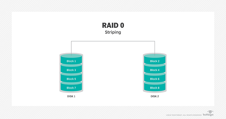
RAID 0: This configuration has striping but no redundancy of data. It offers the best performance but no fault-tolerance
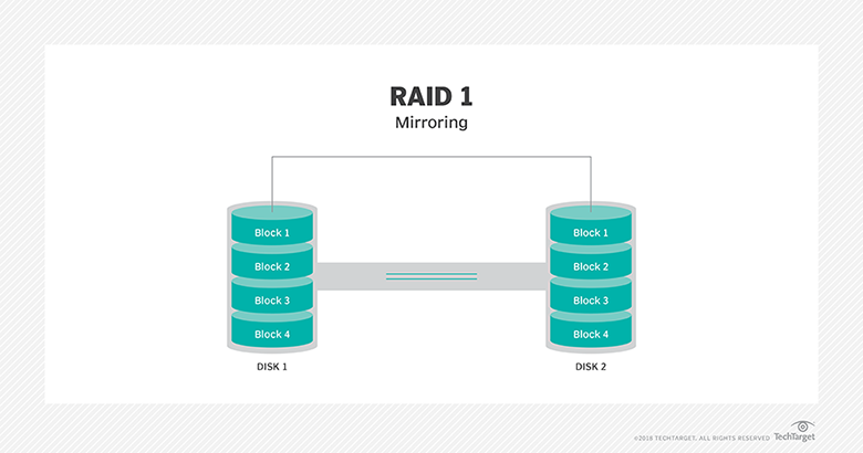
RAID 1: Also known as disk mirroring, this configuration consists of at least two drives that duplicate the storage of data. There is no striping. Read performance is improved since either disk can be read at the same time. Write performance is the same as for single disk storage.
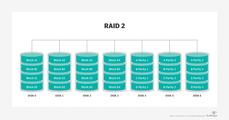
RAID 2: This configuration uses striping across disks with some disks storing error checking and correcting (ECC) information. It has no advantage over RAID 3 and is no longer used.
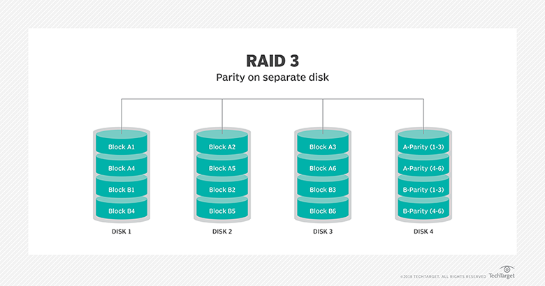
RAID 3: This technique uses striping and dedicates one drive to storing parity information. The embedded ECC information is used to detect errors. Data recovery is accomplished by calculating the exclusive OR (XOR) of the information recorded on the other drives. Since an I/O operation addresses all drives at the same time, RAID 3 cannot overlap I/O. For this reason, RAID 3 is best for single-user systems with long record applications.
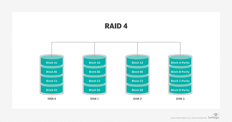
RAID 4: This level uses large stripes, which means you can read records from any single drive. This allows you to use overlapped I/O for read operations. Since all write operations have to update the parity drive, no I/O overlapping is possible. RAID 4 offers no advantage over RAID 5.
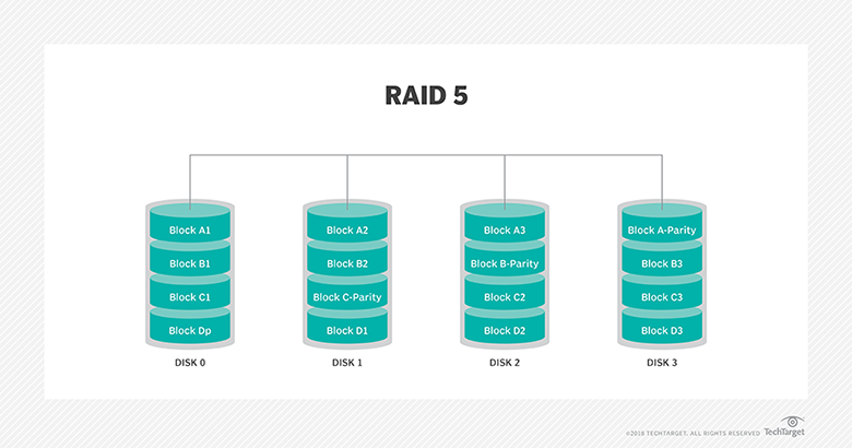
RAID 5: This level is based on block-level striping with parity. The parity information is striped across each drive, allowing the array to function even if one drive were to fail. The array’s architecture allows read and write operations to span multiple drives. This results in performance that is usually better than that of a single drive, but not as high as that of a RAID 0 array. RAID 5 requires at least three disks, but it is often recommended to use at least five disks for performance reasons.
RAID 5 arrays are generally considered to be a poor choice for use on write-intensive systems because of the performance impact associated with writing parity information. When a disk does fail, it can take a long time to rebuild a RAID 5 array. Performance is usually degraded during the rebuild time and the array is vulnerable to an additional disk failure until the rebuild is complete.
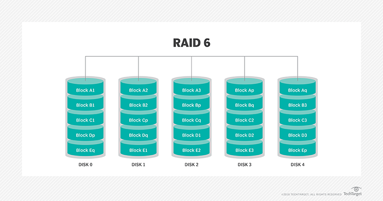
RAID 6: This technique is similar to RAID 5 but includes a second parity scheme that is distributed across the drives in the array. The use of additional parity allows the array to continue to function even if two disks fail simultaneously. However, this extra protection comes at a cost. RAID 6 arrays have a higher cost per gigabyte (GB) and often have slower write performance than RAID 5 arrays.